A bunch of technology enthusiasts started an IoT project to build a water sensor module a few months ago here at QED42. And we would like to share our experience with you.
Water availability has been a pressing concern all over the globe. To counter this, people install water tanks to conserve water. However, currently, a large amount of water and electricity gets wasted due to manual regulation of the water flow via pumps.
This can be improved exponentially if automated. This is where our project steps in. Sophisticated automation tools are available in the market that help control the electrical circuits logically.
| Why an automated water sensor is required?
A traditional water level controller controls the water between two levels with the help of floating balls or a float switch which act as sensors for level detection. Depending on the position of floating balls or the float switch, the electric connection of the pumping motor is switched on or off. However, the controller unit is usually placed at the top of the water tank, where the humidity may corrode the contact points of the sensor switch. This causes the sensor’s switch to malfunction. Meanwhile, since there is no method to detect the water level of the basement water tank, it is possible that the pumping motor will burn if there is a very low/zero water level in the basement water tank.
A traditional water level controller has the advantages of simple structure and low cost but has inherent problems too. Digital electronics to detect and control the water level in an intelligent manner are preferred.
| Water Sensor module
Our team devised a simple yet effective water tank pump switcher circuit. This circuit can be used to maintain the level of water in the overhead water tank within prescribed limits.
| Equipment Used
| Water Sensor Module components
Our water sensor module consists of 4 main components:
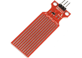
1. Water Sensor module which mainly has 3 pins(+, -, S)
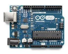
2. Arduino Board
We are using 4 ports in the Arduino board: VCC(5v), GND, A0(analogue port), and 7(digital port).
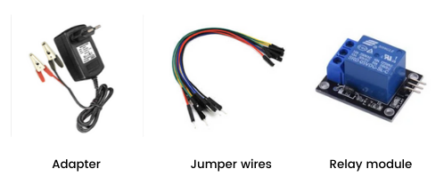
3. Relay SL-C
In the relay, we are using the ground and VCC pins to connect to Arduino. Along with this, we are using the signal port to send signals (pin 7). The relay acts as an electronic switch with 0 as OFF and 1 as ON. There are also NO(Normally Open), NC(Normally Closed), and C(Common Terminal) switches. Here we are using the NO and C ports for our module. We are using the NO switch rather than the NC switch since we want the motor to be operating when the signal is 1. NO switch closes the circuit when the signal is 1.
4. Water Pump
The water pump supplies water whenever it is needed. The positive terminal of the water pump is connected to the NO(normally open) pin of the relay and negative terminal to the 12v power source.